Benefits in brief
- Closed data flow from the flow chart through to the material code for the ERP
- Greater security of communication and project overview
- No multiple data entries, no change maintenance, fewer errors
- Greater consistency accelerates issue of binding quotations
Challenge
Change is a constant companion in the engineering of machinery and plant. In the overall product engineering and development process in which numerous different disciplines and systems usually take part, manual update of modified data in lists, drawings and 3D models not only implies a significant effort but also the heightened risk of the emergence of inconsistencies in data. Often they are only recognised far too late, because it is barely possible to keep an overview of the generally high level of data complexity.
Thus it is not only the correction of errors but also the search for errors that wastes much valuable time. Besides the compromise in data and documentation quality, downtime for the systems can also be a consequence.
Solution
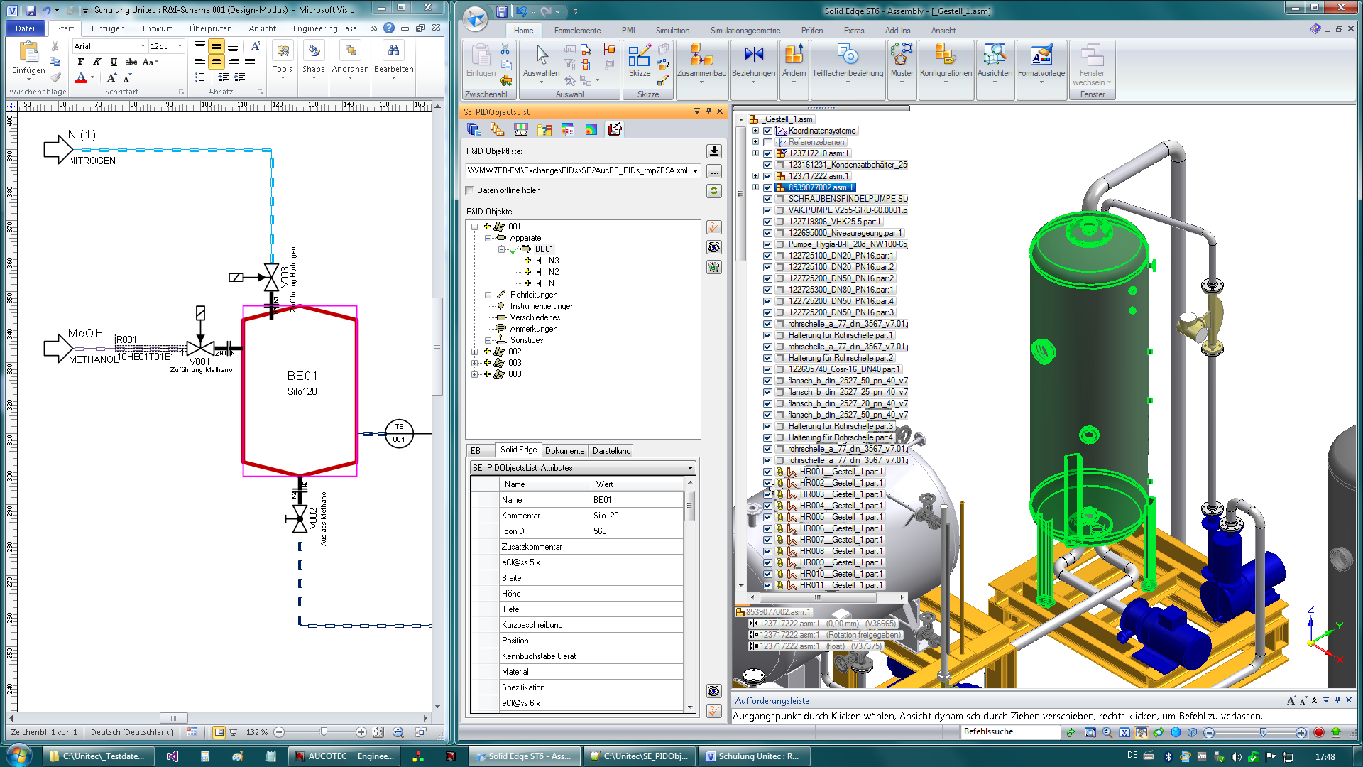
With automated bidirectional exchange of data between the different systems, the engineering process is significantly accelerated, and the considerably improved data consistency brings gains in the quality of documentation. The Solid Edge Plant Connector facilitates this very link between AUCOTEC's Engineering Base (EB) software platform and the 3D CAD tool Solid Edge from Siemens PLM.
Should both systems be deployed on a project then the Solid Edge Plant Connector View enables exchange of the data processed within them to be automated - meaning both speed and consistency.
Through the process chain that is closed by the connector, information flows automatically from the P&ID via 3D into the PLM/ERP system and guarantees the consistency of the data.
In this way for example, the devices, vessels, instruments, loads, pumps or fittings that are planned in the P&ID using EB are linked with the corresponding 3D objects in Solid Edge.
As well as the properties of the items, the structuring of those items is also transferred. Thus all the relevant information is made available in both systems without additional manual effort.
Once the items in EB are linked with those in Solid Edge, any changes are transferred automatically from one system into the other.
Files (e.g. 3D models) that are added to or linked with an item in EB may be directly retrieved or positioned by Solid Edge, which immediately links the items together.
 AUCOTEC AG
Benefits
By integrated engineering - from the flow chart through the 3D model to the bill of materials (BOM) with feedback of the material code into the PLM/ERP - the data loop is closed and synergy is created.
All staff taking part in the process, regardless of their location or area of specialisation, can communicate significantly more securely and receive a far better overview of the up-to-date state of planning.
Multiple data entry and time-consuming and error-prone maintenance of changes are eliminated.
The cross-disciplinary consistency of data prevents errors in reconciliation, quotations can hence be issued more quickly and with a higher level of confidence.
Note: The solution described here represents the full scope of our standard solution. It can of course be expanded in terms of functionality for adaptation to specific requirements. Besides Solid Edge, AUCOTEC integrations are available with a range of further 3D programs.


