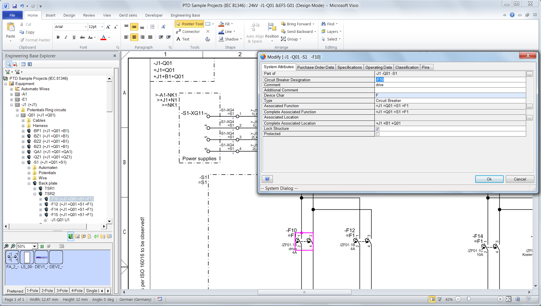
The IEC standard 81346 prescribes plant construction as an object model with three independent views: "Product", "Function" and "Location". It is highly complex and makes the same demands of everyone who wants to and must plan with it. This standard is often not applied in domestic planning tasks because it requires maximum consistency and an overview, which can only be implemented with difficulty using conventional CAD/CAE tools. However, IEC 81346 is mandatory when it comes to international projects.
No need to fear 81346!
AUCOTEC has succeeded in being the first provider of a system that not only graphically maps these required views, but also provides them in an editable and purely alphanumerical form to full depth. The "detour" via the graphic is no longer necessary with AUCOTEC's software system Engineering Base (EB).
The database-driven platform optimally supports the IEC as of version 6.6. EB did not really have to be adapted to the standard. The system was already designed in an object-oriented manner at the outset, thus the object structure can be built, without having to create a single document or device in advance. This independence that is required by the IEC has been a feature of EB for years. Thus IEC requirements are implemented in actual projects more easily and consistently with Engineering Base than with any other system.
One library for everyone and everything
You do not require a second symbol library in order to be able to plan in a standard-compliant manner with Engineering Base. Most tools need this additional library to enable representation of the three aspects in the graphic. Instead, EB uses the existing symbol configurations that are centrally managed in its database and adapts them if necessary to the IEC virtually at the press of a button. However, the symbols can also be used in other standards in parallel.
The configurations can be saved, adapted, copied and exported. Exceptions can be defined centrally. Shapes for layout diagrams, for example, need different designations to circuit diagram symbols. The user has free rein when it comes to detailed planning and customization according to his needs.
 © AUCOTEC AG
Clear multi-frames
The centrally managed configuration of the standard-compliant mapping also affects the frames or multi-frames, for example, the devices that are displayed in a distributed manner due to their complexity and which are represented with a frame in a circuit diagram. Aspects can be easily shown and hidden here also.
If all three aspects are visible in the frame, the system automatically "shortens" according to these aspects within the frame. This means that redundant designations are omitted in frames and thus facilitate readability and understanding considerably.
Automatic knowledge of affiliation
The linking of all existing objects, including their subordinate devices and components, with the relevant location, function and product aspects can be an extremely tedious task, which requires maximum concentration and can result in a lot of errors. Any overview that might have been had is lost very quickly in the process. If a larger object is moved or changed, it becomes enormously complex to disassemble these manually developed linkages and reclassify them.
This is not the case with Engineering Base. Due to its database-driven system, which centrally maintains all plant information and thus also its structure, external or modified projects can be integrated in an existing IEC object model simply via drag & drop. Thus a supplied cabinet including all its devices, from the mounting rail to the final terminal, can be included in the specified location structure with just a few clicks. This is so straightforward because all devices are based on the object that is directly above them hierarchically. As soon as a device is subordinated to another, it knows where it belongs. A switch, for example, which is assigned to a contactor, immediately adopts its function and location aspect.
Assignments are thus more or less automatically "inherited" and do not have to be painstakingly associated manually. This automatic knowledge of affiliations means that only the minimum in terms of association structure must be tracked, which is an invaluable advantage in relation to changes! Manual, more finely graduated assignments, for example, of a particular function aspect to a device, are of course still possible.
 © AUCOTEC AG
 Overview with worksheets
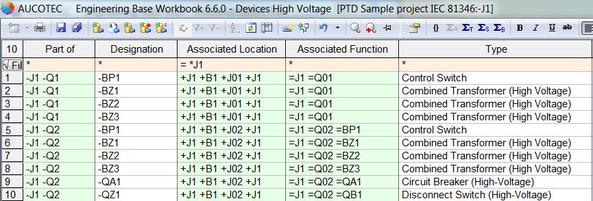
To maintain an optimal overview here, you can use EB's repeatedly proven, Excel-like worksheets (reports). They ensure an exact overview of every aspect of each component or device and enable extremely easy management of all assignments at the same time. The lists can be customized and the information can be filtered. IEC 81346 couldn't be easier!
At an advantage with EB
With Engineering Base, you can implement the internationally binding IEC 81346 practically, easily, consistently and in a time-saving manner. The system can significantly accelerate the widespread use and acceptance of the standard so that more and more projects and engineers can benefit from the advantages provided by such standardization.
Projects can be planned and implemented highly conveniently in terms of the standard because the extra work required by the IEC is reduced to a minimum with EB.
The aspect association of subordinate devices is largely automated and is thus accordingly correct. The management of assignments is uniquely clear. EB eliminates the need for an additional symbol library in which the shapes also show the location aspect. The aspects can be simply shown or hidden for symbols as well as for frames.


